Rohde & Schwarz solution
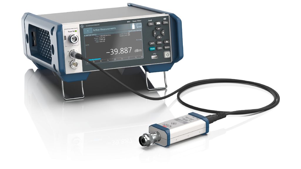
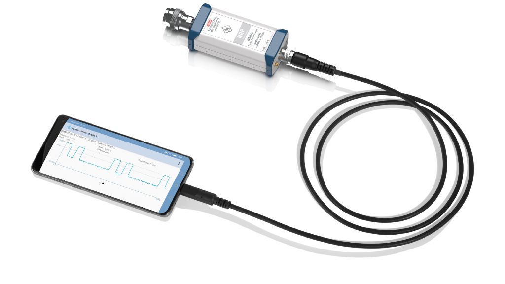
The best way to perform precise power measurements is to use a device designed for the very task of measuring power with top precision, i.e. an RF power sensor. RF power sensors are able to measure power with precision that is an order of magnitude higher than an oscilloscope or even a high-end spectrum analyzer.
Precise power measurements are best performed with an RF power sensor since these devices can measure absolute power with extreme precision. However, state-of-theart power sensors usually require an investment that may not be acceptable for hobbyists, universities or small R&D service labs. The new R&S®NRPxE series of diode power sensors also takes into account these cost considerations.
It is the most affordable RF power sensor line in the Rohde & Schwarz portfolio, yet it supports highly precise power measurements. For a typical LoRa device verification test setup, further equipment is required:
- A characterized signal chain composed of high-quality RF components coupled to the DUT
- Cables and connectors
- Attenuators and couplers to get the signal to approx. 0 dBm, which is the ideal level for RF power sensors
- A vector network analyzer (VNA) to characterize the signal chain
The measurement task is comprised of the following steps:
1. Set up and characterize the signal path from the device.
2. Measure output signal of LoRa devices with an RF power sensor, taking into account measurement losses.
3. Select best LoRa device and tune the power to an adequate level at the antenna feedpoint.
4. Check the device subsequently while it is in regular use.
A few additional tips and best practices are described below:
- Characterize the coupler and attenuator with an affordable VNA, then upload the resulting .s2p file to the R&S®NRPxE diode power sensor and activate the correction data to account for signal path loss.
- Apply proper torque using a torque wrench.
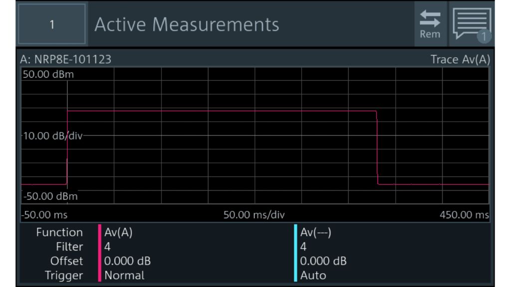
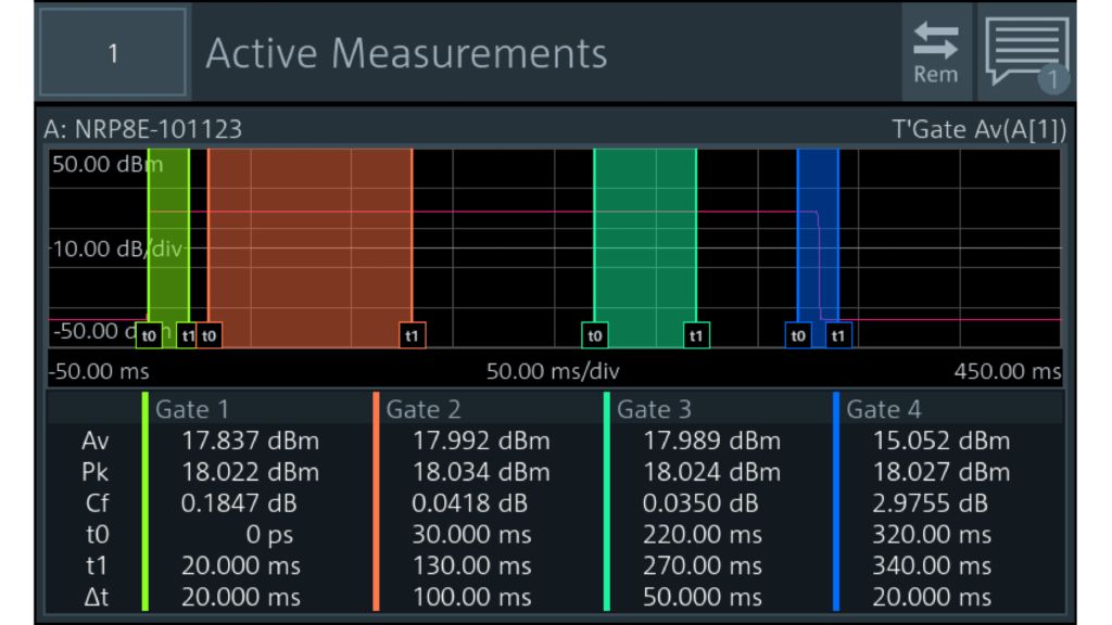
- With a modulated or chirp/burst/pulse signal, set the aperture time to the integer period duration, ideally at least three periods.
- The "duty cycle" functionality accounts for signal on/off times in order to measure the real average power.
- Using the averaging filter, which utilizes multiple aperture cycles to calculate a more precise average, improves the measurement result even further.


