Wideband modulated load pull

Wideband modulated load pull signals likes those used in final deployments provide true insight into RF frontend performance. However, RF amplifiers behave differently when the impedance changes. RF amplifiers behave differently with varying impedances when they drive signals into a wideband antenna and their behavior cannot be predicted or calculated.

Many RF frontends and RF amplifiers in communications systems drive wideband modulated signals into antenna systems. Since the frontends are used over a wider frequency range with multiple transmission bands, they see varying impedances as loads. Such dispersive loads can have a significant impact on amplifier gain and distortion.

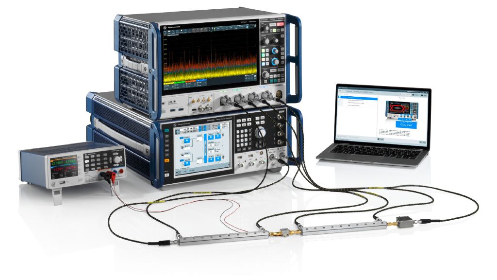
Wideband modulated load pull solution using the R&S®RTP164B and the R&S®SMW200A
Wideband modulated load pull solution using the R&S®RTP164B high-performance oscilloscope and the R&S®SMW200A vector signal generator
Open Lightbox

Your task

RF power amplifier engineers want the best device performance in their target application. Most RF systems are nominally 50 Ω systems, but the real impedance for the RF frontend can differ greatly. An antenna can present loads to an amplifier within a wide frequency range. The impedance towards the amplifier can change significantly from below 20 Ω to above 100 Ω. Unfortunately, no model can predict the gain, efficiency or distortion behavior validated in essential key performance indicators (KPI), such as error vector magnitude (EVM) or adjacent channel leakage ratio (ACLR). The only way to know whether an RF frontend can cope with a dispersive load is to test it.

Block diagram of a basic passive vector-receiver load pull setup
Open Lightbox

Rohde & Schwarz solution

Rohde & Schwarz takes a unique approach to wideband modulated load pull. Traditionally, load pull systems use a vector network analyzer (VNA) plus mechanical tuners to create a passive load pull system that presents different impedances to a transistor.

Here, the VNA is replaced by a vector signal generator and a vector signal analyzer to support various modulated signals and their evaluation in modulated tests with different load conditions. A tuner is used to create the wanted impedance on the output side of the test device.

Traditional modulated load pull scenario
Traditional modulated load pull scenario. A vector signal generator used for the stimulus and a vector signal analyzer for the measurements
Wideband modulated load pull setup

The approach has been used and proven for years with narrowband signals. When signal bandwidths increase, the tuner inherent frequency response and group delay falsify measurements and a different approach is required.

Rohde & Schwarz developed a solution that uses the concept of an active load pull system that creates the desired impedance with an active signal injection on the DUT output side and not a mechanical tuner. The concept is shown in the “Wideband modulated load pull setup” figure.

The solution uses an R&S®RTP oscilloscope with four ports to measure the forward and reverse waves on the DUT input and output sides. R&S®RTP oscilloscopes have time and phase synchronization plus a high recording bandwidth. The R&S®SMW200A vector signal generator provides a test signal as input to the device and the tune signal to create the desired impedance. Stable and user controllable timing and phase conditions between the two signals are very important. R&S®RTP-K98 modulated load pull software controls the complete setup and guides the user through calibrations and measurements. Good results were achieved with Marki Microwave CD10-0106 dual directional couplers on the DUT input and output.

The solution uses an R&S®RTP oscilloscope with four ports to measure the forward and reverse waves on the DUT input and output sides. R&S®RTP oscilloscopes have time and phase synchronization plus a high recording bandwidth. The R&S®SMW200A vector signal generator provides a test signal as input to the device and the tune signal to create the desired impedance. Stable and user controllable timing and phase conditions between the two signals are very important. R&S®RTP-K98 modulated load pull software controls the complete setup and guides the user through calibrations and measurements. Good results were achieved with Marki Microwave CD10-0106 dual directional couplers on the DUT input and output.

Enhanced wideband modulated load pull setup
Open Lightbox

Higher power DUTs and a wider tuning range need an amplifier such as the R&S®SAM100 system amplifier that can be looped in to boost the tune signal. To avoid unwanted amplifier or signal generator load pull, one or more circulators can be added for decoupling.

The signal bandwidth and covered frequency range are only limited by the instrument configuration. Up to 2 GHz of signal bandwidth can be supported, which covers major communications systems. The maximum frequency of 8 GHz means the FR1 band up to 7.125 GHz for mobile and Wi-Fi applications is covered.

Maximum output power, gain, EVM or ACLR can be directly measured with the sampled b2 waveform. If the DUT is very high performance, the b2 signal can be split and a signal and spectrum analyzer used, such as the R&S®FSVA3000 with enhanced dynamic range and excellent EVM measurement capabilities.

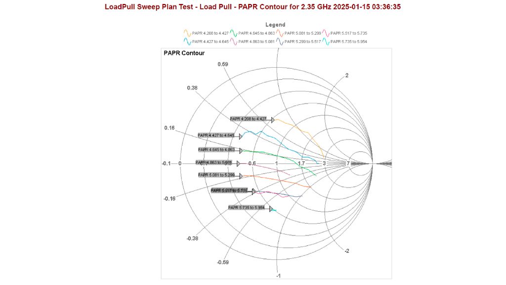
Contour plot for peak-to-average power ratios (PAPR) as a measure for modulation distortion of the DUT taken by R&S®RTP-K98
Open Lightbox

Application

As with any similar network analyzer measurement, a system level calibration is required to tune to a certain point on the Smith chart accurately and reliably. All accessories in the system shall be present during the calibration, including amplifier and circulators, to govern their influence. The R&S®RTP-K98 software guides the process with a visual display showing each calibration step. The calibration follows a two-step routine starting with an open, short and match (OSM) calibration on the DUT input plane followed by a transfer to its output side using a known through.

The tune signal should differ from the input signal for greater accuracy. Though it may sound contradictory, the explanation is simple: The RF frontend adds distortion to the signal and the output signal b2 differs from the input signal a1. The tune signal a2 needs to be the same as b2 for accuracy. The application first records the DUT output signal b2 for each frequency and level point and uses this as the tune signal a2 which includes the individual distortion added by the DUT for a given scenario before tuning to different impedance points.

The R&S®RTP-K98 application software provides single impedance tuning for single point checks or, when controlled from an external user program, in a step-by-step approach. A sweep plan can create a measurement sequence across different impedances for multiple frequencies and levels to create contour plots of device KPIs such as gain, maximum output power or EVM. Since the impedance variation simply involves changing the amplitude and phase relationship between the two channels in the vector signal generator, tuning is very fast.

The automatically created test report contains all the results. In addition, all test data can be compiled in easily accessable formats such as CSV for postprocesssing.

Digital predistortion (DPD) is available by looping in R&S®VSE-K18 amplifier measurement software with the direct DPD process for the R&S®RTP oscilloscope. Using custom, predistorted signals and external evaluation, makes any user-defined DPD available as well.

The solution includes a powerful extension that helps deembed dispersive impedances for greater realism and opens up potential new applications. The impedance of an antenna is highly dependent on the frequency. Signal bandwidths of 100 MHz and more meant that even in band, this variation can no longer be neglected. The solution can use an S1P file describing the behavior of the antenna to offer a realistic scenario including frequency variation. Two S2P files can be deembedded to recreate a matching network or a bandpass filter. While using different S2P files for different matching networks, the matching network influence can be easily optimized and its design adopted in a simulation environment for an S2P representation. Even hybrid systems could be assembled while loading the tuner data as an S2P file into the R&S®RTP-K98 software for deembedding.

Finally, this oscilloscope-based solution can be used to match with envelope tracking with a second R&S®SMW200A, as well as true time-domain information about the DUT response.

Dispersive impedance and deembedding
Open Lightbox

Summary

The wideband modulated load pull solution using standard lab instruments is a fast, versatile and cost-efficient solution for accurate impedance tuning. The flexibility of the instruments enable wide signal and application coverage.