Ultra-wideband interference testing
Ensure that UWB applications will function in the presence of in-band or near-band radio services.

Ensure that UWB applications will function in the presence of in-band or near-band radio services.


Introdution
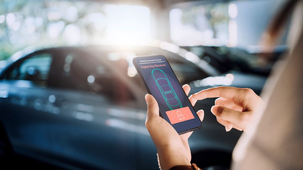
Ultra-wideband (UWB) technology enables precise positioning and communications over short distances, offering numerous benefits for secure ranging applications. This technology uses short bursts of radio pulses occupying a bandwidth of more than 500 MHz and operating in the frequency spectrum, typically in the 3.1 GHz to 10.6 GHz range. It enables applications like real-time asset tracking and navigation as well as secure access control and tapfree mobile payment. In the context of automotive applications, UWB was first introduced for digital key applications as defined by the Car Connectivity Consortium (CCC). With its high accuracy, reliability and security, UWB is well-suited to a range of automotive applications beyond secure keyless entry systems, applications such as child presence detection systems and gesture control.
UWB is defined by low transmission power, e.g. –41.3 dBm (1 MHz), which enables operation in frequency bands also used by other radio services. It is therefore critical to test whether UWB applications – in particular, security-relevant applications – will be disrupted by radio services. Interference signals can come from different sources, one of the most common being interference caused by other radio services operating within or near the UWB frequency band. Potential sources of such interference include Wi-Fi operating in the 6 GHz band, C-V2x and future cellular networks.
Your task
During development and quality assurance, it is necessary to investigate the impact of existing and future radio services on UWB applications. This is the only way to ensure that security-relevant UWB applications function properly in the long term and take appropriate countermeasures to avoid interference.
Rohde & Schwarz solution
Secure distance measurements are an essential feature of various UWB applications. Therefore, exact time of flight (ToF) measurements are required when validating UWB devices and chipsets as well as for antenna calibration. Additionally, ToF can be used to investigate the influence of interference signals by observing the ToF in the presence of an interference signal at different frequencies and power levels. Interference signals can severely degrade the reception of weak UWB signals.
For accurate ToF measurements and receiver sensitivity measurements, Rohde & Schwarz provides an easy to set up test solution. The R&S®CMP200 radio communication tester used in combination with the R&S®CM-Z310A UWB remote radio head, including an RF power splitter/combiner and a selection of attenuators make it possible to perform ToF and receiver sensitivity measurements without the need for additional calibration or path delay measurements.
Interference measurements can be conducted in a controlled environment or over the air (OTA). The R&S®CMQ200 is ideal for UWB OTA testing. It offers a frequency range from 0.3 GHz to 14 GHz and over 80 dB shielding effectiveness. The chamber can be flexibly configured to meet customer testing needs.
To generate an interfering signal, a vector signal generator like the R&S®SMM100A is used. This generator provides remarkably good RF characteristics across the entire frequency range from 100 kHz to 44 GHz. It also covers the bands below 6 GHz used by existing wireless standards as well as the newly defined bands for 5G NR FR1 and Wi-Fi 7.


Fig. 2: Influence of a Wi-Fi signal with a bandwidth of 20 MHz (blue) and 320 MHz (red) on UBW receiver sensitivity
Application
Fig. 1 shows the test setup for UWB interference testing. The interference signal generated by the R&S®SMM100A is fed to the UWB device under test (DUT) via an RF power combiner (upper image). The interferer is fed to the UWB DUT OTA via an antenna in the R&S®CMQ200 chamber (lower image). For the ToF and receiver sensitivity measurement, the R&S®CM-Z310A UWB remote radio head is connected to the R&S®CMP200 radio communication tester. Both measurements are performed using the R&S®WMT wireless manufacturing test tool and its built-in UWB PHY test suite, controlled by an external PC.
The R&S®WMT tool is a Python based software solution for chipset and module RF testing of 5G NR, Wi-Fi, Bluetooth® and UWB (including UWB TX, RX, ToF and AoA testing). It is tailored for high volume production testing and fully automated R&D applications. In addition, the R&S®WMT controls the DUT using standard FiRa UCI command communications through the control interface (COM port).
During ToF or receiver sensitivity measurements, an interference signal is added, either conducted via the power coupler or OTA through an antenna at specific frequencies and variable power levels. To test the influence of the interferer on the DUT, the interference signal level is increased to a specified value.
Testers can also observe whether the ToF value changes or the ToF measurement is impossible due to the interferer. Fig. 2 shows the measurement result of the UWB receiver sensitivity on CH5 (6489.6 MHz) in the presence of a Wi-Fi signal with different signal bandwidths (20 MHz and 320 MHz at 6.245 MHz).
Summary
Ensure reliable and secure UWB applications with the Rohde & Schwarz comprehensive test solution. It enables accurate ToF measurements, interference testing and certification of UWB devices and chipsets for long-term functionality.


Fig. 1: Test setup for UWB interference testing: conducted (above) and OTA (below)
The Bluetooth® word mark and logos are registered trademarks owned by Bluetooth SIG, Inc. and any use of such marks by Rohde & Schwarz is under license.