August 26, 2025 | by Arnd Sibila


Scenario 1: Low DL and UL throughput
A private 5G network operating in band n78 (3700–3740 MHz) with a TDD pattern of DDDFU (2.5 ms periodicity) experienced suboptimal throughput. Expected DL throughput was ~300 Mbps, but actual measurements showed tremendously low throughput of ~ 30 Mbps, while UL throughput dropped from ~60 Mbps to ~12 Mbps.
Manual troubleshooting process
1. RF metrics analysis:
DL RSRP (~-60 dBm) and SINR (~35 dB) were strong, indicating no DL interference.
CSI-RS CQI (Channel Quality Indicator) reported by the UE suggested no DL issues (CQI 10–11, implying 64QAM capability).
2. MCS statistics:
Despite good RF conditions, QPSK was predominantly used for both DL and UL traffic, far below the expected 64QAM.
3. Transmission statistics:
Retransmission (Re-Tx) rates were abnormally high: ~66% of DL samples were retransmissions, exceeding the typical 10% target.
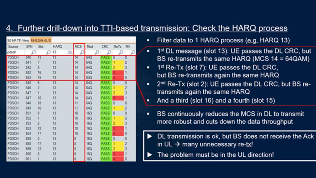
4. TTI-based analysis: HARQ process drill-down
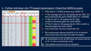
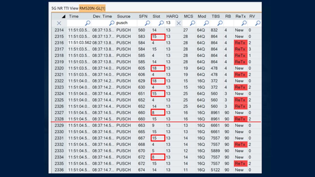
Analysis of the Hybrid Automatic Repeat Request (HARQ) process revealed that the base station (BS) failed to receive acknowledgments (Acks) in the UL. For example, in HARQ process 13, the UE passed CRC checks, but the BS repeatedly retransmitted the same data, reducing MCS to ensure robustness.
5. Root cause analysis by expert:
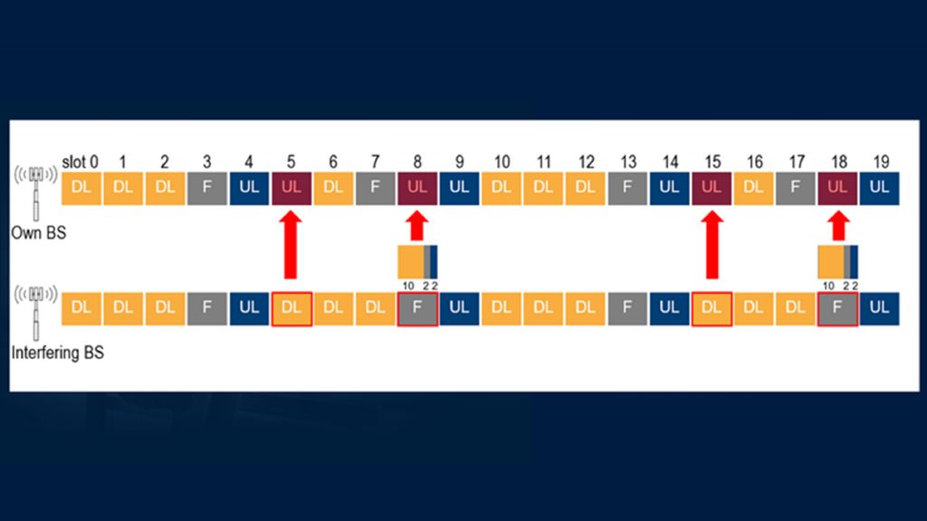
The BS did not receive UL Acks due to UL radio problems. Another BS transmitted at the wrong time, creating interference in UL slots, likely caused by non-synchronized networks. This UL radio problem is the root cause for low DL and UL throughput.
Automatic smart troubleshooting
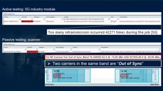
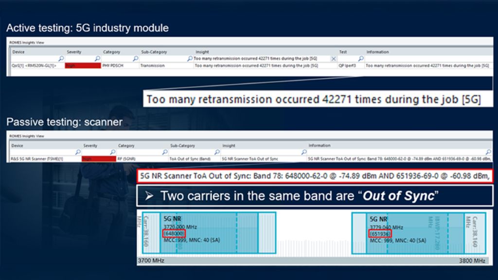
The ROMES software (in combination with the 5G modem test device – active testing) comes with predefined insights, so the user does not need to perform all the manual steps described above. In this case, the insight automatically provided says: “Too many retransmissions occurred”.
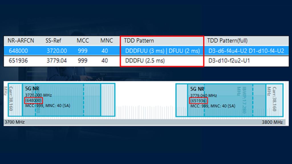
In addition to specifically identifying the problem, the ROMES software (together with the R&S®TSMx network scanner - passive testing) comes also with cause identification. In this case, two carriers operate in the same band (3700 MHz) out of sync, i.e. UL slots are disrupted by DL transmissions from the interfering BS.
Scenario 2: Low UL throughput only
In this scenario a private 5G networks is intentionally configured for higher UL capacity (TDD pattern DDDFUU DFUU, 5 ms periodicity) to cope with more UL-heavy use cases like AGV with cameras or supervision cameras (CCTV). The experienced UL throughput of ~40 Mbps was a factor of 3 lower than the targeted UL throughput of ~ 120 Mbps), while DL performance remained normal.
Manual troubleshooting process
1. RF and MCS analysis:
DL RF metrics were good, but UL MCS (16QAM) was suboptimal.
2. Transmission statistics:
Compared to the scenario 1, more UL slots are used here, and all eight UL slots are equally used for transmission.
3. TTI-based analysis: HARQ process drill-down
Re-Tx rate was high (~30%) at the beginning of the UL test, prompting the BS scheduler to adapt the modulation and coding scheme (MCS). Analysis of the HARQ process (here: HARQ process 13) revealed that the base station (BS) reduces the MCS from 27 to 11 in subsequent radio frames to balance reliability and throughput. This is the wanted behavior of the scheduler to control the Re-Tx rate to ~ 10%.
4. Timeslot-based analysis
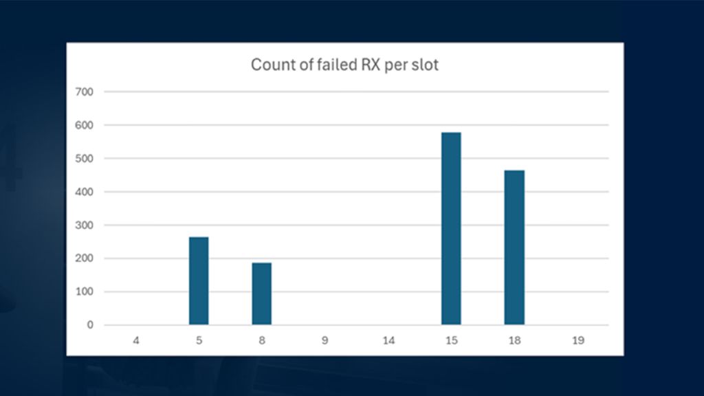
UL transmissions often failed in slots 5/15 and 8/18, with no failures in adjacent slots (4/14, 9/19). This indicated timeslot-dependent interference.
5. Root cause analysis by expert:
The affected uplink (UL) slots show signs of unwanted power. The most likely cause in these cases is a neighboring base station (BS) operating on a different Time Division Duplex (TDD) downlink/uplink (DL/UL) pattern. As a result, its downlink slots are overlapping with the uplink slots of the target network, leading to interference that disrupts communication.
Automatic smart troubleshooting
The automated insight generation of the ROMES software based on the R&S®TSMx network scanner data immediately detected the two problematic BS signals and at the same time identified the different DL/UL TDD patterns of the two signals indicating a potential problem for the network having a higher number of UL slots.
Summary
The root causes for the two scenarios were unwanted power from an interfering base station (due to non-synchronized networks or networks with different TDD DL/UL patterns).
The manual troubleshooting process requires expert knowledge and mobile network testing tools that provides the needed insights like the TTI-based transmission analysis.
Ideally, this expert knowledge is partly integrated into the tools that directly provide the root cause for the problems allowing for a smart automatic troubleshooting process.
One question is still open: Why do we have interference between the two networks, if they operate in different frequency carriers (even respecting a guard band of 20 MHz between them).
Technology: Intermodulation
Non-linear components cause intermodulation products and harmonics. A base station receiver (designed to be strictly linear) could become non-linear, if strong signals reach its input.
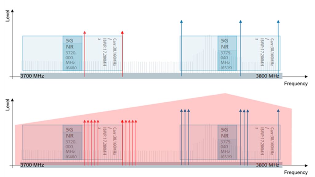
Intermodulation products (e.g., third-order 2f1 - f2, 2f2 - f1, and higher order) can fall into adjacent frequency ranges, degrading signal quality. In TDD systems, where uplink (UL) and downlink (DL) share the same frequency but alternate in time, intermodulation is particularly problematic. For example, multiple carriers in the 3700 MHz band can produce third-order- and higher-order-intermodulation products that interfere with UL slots, creating a "noise floor" that masks legitimate signals and reduces UL performance.
The issue is compounded by OFDM (Orthogonal Frequency Division Multiplexing) signals, which use many subcarriers. As subcarrier count increases (i.e. the network load is higher), intermodulation products multiply, further degrading performance. This is visualized in frequency plots showing overlapping signals across bands.
Solutions to cope with intermodulation include:
1. Synchronization: Aligning TDD patterns to avoid overlapping UL/DL slots.
2. Filtering: Using diplexers in FDD systems to isolate UL/DL signals (not possible in TDD networks).
3. Power Management: Keeping signals within a receiver’s linear range.
Intermodulation is a systemic issue in dense, multi-carrier environments. Addressing it requires proactive monitoring, synchronization, and hardware optimization to maintain signal integrity and network performance.
Key solutions and recommendations
1. Network synchronization:
- Ensure all networks / carriers in the same band are synchronized to avoid overlapping UL/DL slots. Non-synchronized networks is a failure case.
2. TDD pattern alignment
- Ensure all networks / carriers use the same TDD DL/UL pattern. If more UL resources are required, special countermeasures need to be respected to avoid intermodulation products and performance degradations in neighboring carriers.
3. Intermodulation mitigation:
- Deploy filters (e.g., diplexers for FDD networks) to prevent DL signals from reaching the receiver. For TDD networks, avoid overloading the receiver with high-power signals to reduce non-linear intermodulation.
4. Regular measurements:
- Private networks with intentionally higher UL capacity (e.g., industrial IoT) are particularly vulnerable to interference. Regular testing is essential to identify synchronization issues and intermodulation effects. Be aware that a one-time measurement after deployment is not sufficient, since public networks in the same location might change (new BS sites might be installed, antenna directions or transmit powers can be changed, network load over time can be higher, etc.).
- Active (ROMES, 5G industry module) and passive testing (ROMES, R&S®TSMx network scanner) enable real-time root-cause analysis in field. R&S®SmartAnalytics will add this detailed TTI-based analysis capabilities in post processing.
Benefits of the more automated troubleshooting process
The automated troubleshooting solution proactively identifies network issues that manual processes often miss, preventing service degradation and maintaining optimal Quality of Experience (QoE) for end users and critical applications. Automated root cause analysis dramatically accelerates troubleshooting, allowing engineers to resolve problems faster and more efficiently. Ultimately, this frees skilled personnel from repetitive tasks, enabling them to focus on strategic network optimization and improved overall system reliability.


