DDR – double data rate memory

DDR – double data rate memory

Step-by-step guide: Advanced probing in DDR3/DDR4 memory design

More information

DDR memory testing

As is usually the case with a high-speed data bus, oscilloscopes can handle virtually all of the requirements for testing DDR memories data transfers and signal properties, both during development and for compliance testing. At the PCB layer, network analyzers can provide the highest level of accuracy for signal integrity testing of the signal channels.

DDR basics

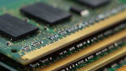
DDR SDRAM technology for storing data and enabling a fast data exchange with a processor was introduced in 1998 and is now in its fifth generation. DDR stands for “double” data rate; because there are two data bits transfers per clock cycle. DDR SDRAMs dominates today main memory for all types ofprocessors. With each generation of DDR SDRAM, data transfer rates and clock frequency have increased, while operating voltages and power consumption have decreased. The huge increase in performance and the lack of backward compatibility between generations means that multiple generations of DDR are in common use – from DDR5, introduced in top-end PCs in 2021, back to DDR2, introduced in 2003.

Your DDR challenges

  • DDR versions are not compatible; you need to choose which version is most suitable for a particular project; considering among others performance requirements, design complexity or part costs and availability.
  • DDRuses bi-directional data transfer; how do you determine for signal integrity testing whether data is being written to or read from memory?
  • Test equipment budget is limited; which test equipment meets your needs and your budget best?
  • DDR compliance testing conformant to the respective JEDEC standard is complex, if the results are to be valid; you need to be sure you are conducting compliance tests correctly.
  • DDR memory chips come typically in BGA packages. If there is no access to vias on the backside, interposers have to be added between the memory chip and the board. For measurements to be meaningful, the influences of the test setup need to be accounted for.

Our DDR testing solutions

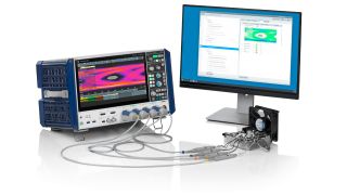
The R&S®RTO64 and R&S®RTP oscilloscopes provide dedicated application optins for conducting DDR3, DDR4 and DDR5 memory interface tests. The DDR options for both oscilloscopes are unique on the market for supporting READ/ WRITE decoding DDR signals, enabling eye diagram functionality and providing automated compliance tests to the official JEDEC specifications of the DDR & LPDDR standards.

Most of the problems designers are facing with DDR memories will be in the board layout; issues such as inadequate bandwidth, cross-coupling from other functional blocks, mismatches in impedance, or jitter. Both R&S oscilloscope families feature a wide range of functions for debugging signal integrity issues , starting from Zone-Trigger, Advance Eye Analysis, Jitter and Noice decomposition, or Power Integrity analysis, and more.

The bandwidth of the oscilloscope is the most significant factor for determining which DDR generation at which data rate can be tested. For system testing the bandwidth should cover the 3rd to the 5th harmonic of the fundamental frequency of the tested signal.

  • DDR3 , DDR3L , and LPDDR3 (1.2v) require option K91 on an R&S®RTO64 or R&S®RTP.
    For DDR3 data rates up to 1.6 GBps an R&S®RTO64 with 4 GHz bandwidth is more than adequate, higher data rates up to the 2.133 Gbps DDR3 an oscilloscope bandwith of 6 GHz is recommended.
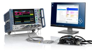
  • DDR4 or LPDDR4 require option K93 and an 8 GHz R&S®RTP084. To verify the rise times on the data and control signals, an R&S®RTP164B is recommended.
  • DDR5 testing is addressed with option RTP-K94, while LPDDR5 requires option RTP-K95 and the 16 GHz RTP model RTP164B.

To simplify and automate compliance procedures with either of these options, the R&S®ScopeSuite software provides:

  • The comprehensive graphical Wizard to guide through the compliance procedures from beginning to end.
  • Automated control of all necessary oscilloscope settings and compliance test sequences.
  • Configurable test reports to document the test results.

Rohde & Schwarz also supplies all the necessary accessories such as highspeed probes with flexible solder-in solutions and deembedding software for the compensation of third party test fixtures from Nexus Technologies or EyeKnowHow for DDR debug, signal integrity testing, validation and compliance testing.

For signal channel testing between DDR modules and processor, Rohde & Schwarz network analyzers (R&S®ZNA, R&S®ZNB) provide signal integrity measurements with a dynamic range and maximum bandwidth that comfortably exceeds all DDR requirements. For both analyzer families, option K2 plus K20 provides time domain analysis including eye diagrams and simultaneous frequency domain analysis.

Benefits of our DDR memory test solutions

  • Comprehensive testing from design debugging to compliance test in the frequency and time domains of DDR devices, interposers, and connectors, provided by test equipment meeting all requirements including oscilloscopes, vector network analyzers, probes, and solder-in solutions.
  • Automatic separation of READ/WRITE bursts. As DDR uses bi-directional interfaces, Read and Write signal bursts must be distinguished from each other before any analysis can take place. With the R&S DDR options the RTO6/ RTP oscilloscopes decode Read/Write bursts automatically.
  • Intuitive, both quick and long-duration signal integrity testing.
    The powerful Zone-Trigger allows to focus the analysis on dedicated data sequences. With the Data Eye analysis tools, investigate any problems with signal integrity and perform mask tests over longer periods. Use the advanced jitter analysis tools to investigate interferer on the clock or verify your margin.
  • Be confident that compliance test is carried out correctly. Fully illustrated step-by-step instructions from connecting the oscilloscope, the probes, the test fixture and the device under test, through to the end of the test sequence, including running individual tests, changing parameters in mid test, and setting user-defined limits.
Sign up for our newsletter

Stay up to date on upcoming trends and latest applications.

Sign up for our newsletter

Request information

Do you have questions or need additional information? Simply fill out this form and we will get right back to you.

Marketing permission

Your request has been sent successfully. We will contact you shortly.
An error is occurred, please try it again later.